Cable conveyor rollers support and guide the cable before and after the powered machine. Ordering a cable pusher alone does not define how the cable will pass over the ground, around a bend or into a duct.
Start with a route sketch and select accessories for each change in direction or support condition. Keep the powered conveyor’s gripping system separate from the passive rollers used along the route. Each item needs its own suitability check.
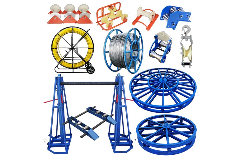
Match the accessory to its position
| Route position | Accessory to discuss | Details to send |
|---|---|---|
| Straight ground or trench run | Straight-line or ground support roller | Cable weight, diameter, ground conditions and available width |
| Horizontal change of direction | Corner roller arrangement or suitable sheave system | Bend geometry, cable bending limit and expected loading |
| Duct or manhole entry | Entry guide, lead-in roller or bellmouth arrangement | Opening dimensions, approach angle and attachment conditions |
| Elevated cable tray | Tray-mounted support rollers and direction-change supports | Tray dimensions, mounting details and approved support capacity |
These are enquiry categories, not a universal installation layout. A single corner roller may guide cable locally without providing the bend radius required for the complete turn. Ask for an arrangement drawing instead of choosing by the product name alone.
Check the cable limits and accessory ratings separately
Confirm the accessory’s cable diameter capacity, rated load and mounting method. Ask what direction the load rating applies to. The conveyor’s maximum force does not establish the safe working load of every roller, bracket or supporting structure.
TT Technologies lists cable rollers and corner rollers as separate accessories with their own dimensions and load information. Those ratings apply to its specified products; they should not be assigned to visually similar accessories from another supplier.
Why there is no single roller spacing for every cable
Southwire’s Power Cable Manual, Chapter 7, explains that tray roller spacing varies with cable weight, tension, construction and roller height. It also calls for adequate bend radii and attention to sidewall pressure at changes of direction.
Have the responsible installation team determine the layout using the actual cable manufacturer’s instructions and site conditions. Do not treat a spacing copied from another project as an approved design. Rollers should turn freely and the installed arrangement should keep the cable clear of damaging contact surfaces.
Prepare an accessory schedule for the supplier
- Label each route section and mark bends, entries and elevation changes.
- Attach the cable datasheet, including outside diameter and weight per metre.
- Identify the proposed conveyor and where cable enters and leaves it.
- Provide opening dimensions, support details and mounting photos.
- Ask for model numbers, quantities, ratings and connection or mounting drawings.
- Separate included items, optional accessories and items supplied locally.
Coordinate the package with the cable conveyor
The Conveyor Transmitter 600 page lists a 1–10 cm cable diameter range. Confirm the rollers and guides against the actual cable, rather than assuming every accessory accepts the machine’s full range. Its listed machine weight is also separate from an accessory’s load rating.
Review our cable installation accessories and multi-layer tray mounting checklist. Request a conveyor-and-accessory quotation with the labelled route sketch so the proposed package can be reviewed before ordering.