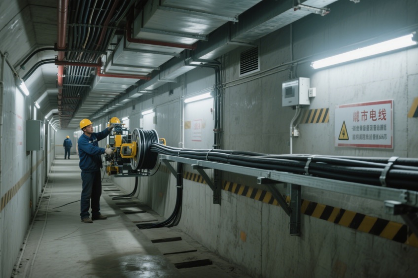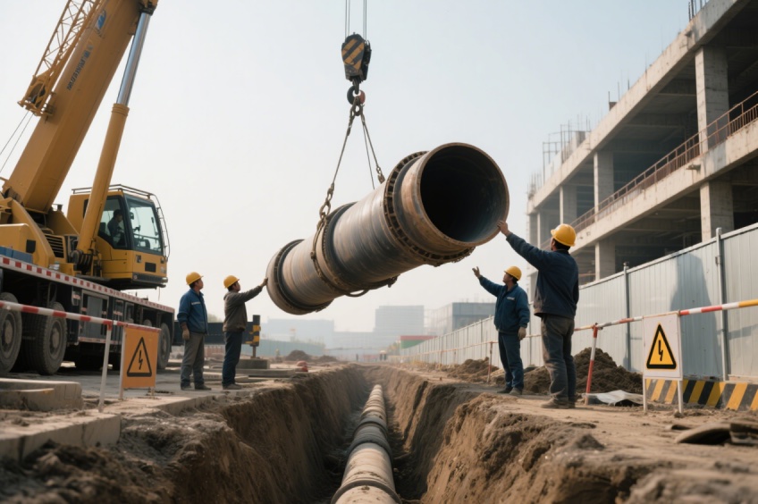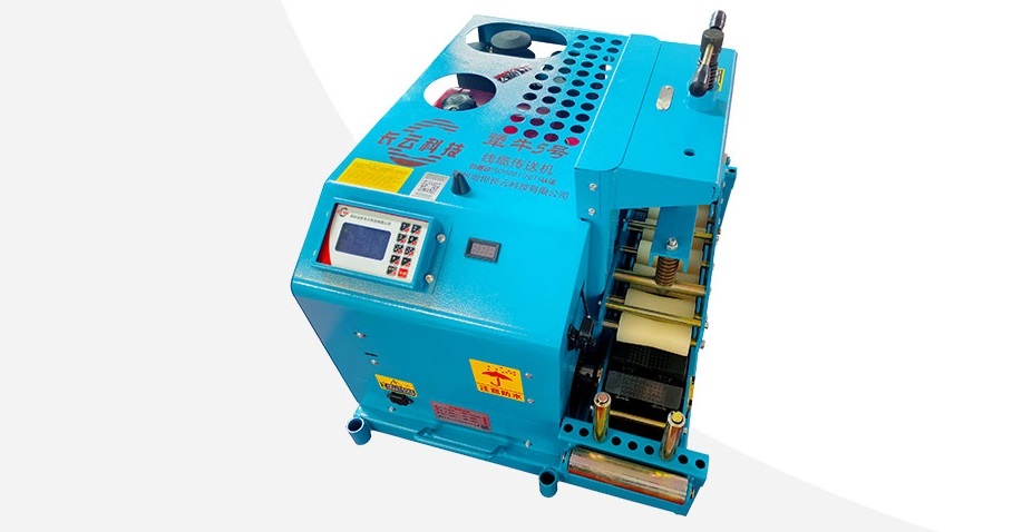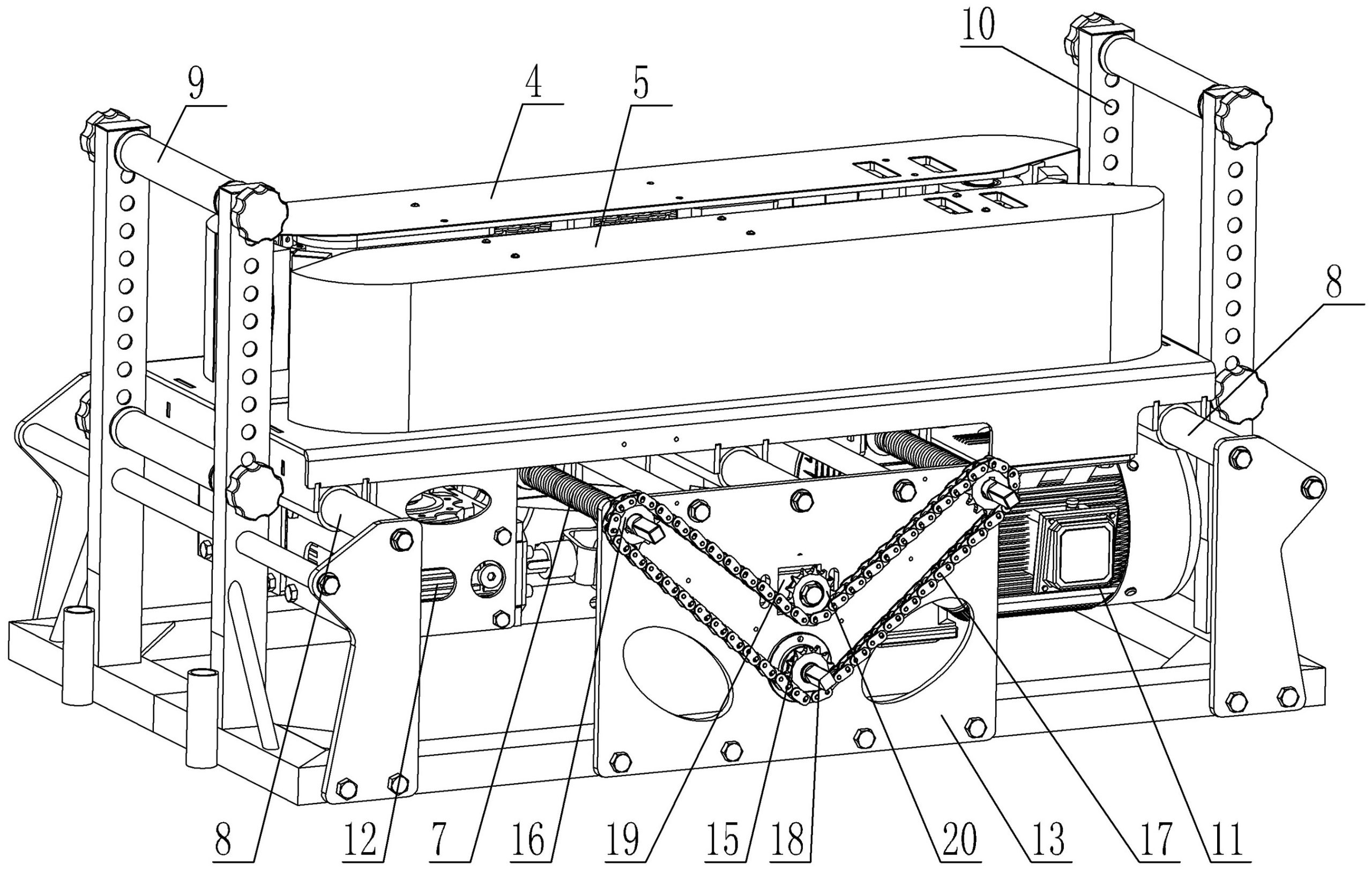
How many cable pushers do you need for a long installation route? There is no reliable answer based on total metres alone. Start with the cable’s handling limits, the route geometry and the accessible equipment positions. The final quantity and placement require a project-specific installation review.
This guide helps contractors prepare a useful equipment enquiry. It is not a calculation method or an approved installation plan, and the example below is illustrative rather than a completed project.
Why a fixed distance between cable pushers can be misleading
Two routes of equal length can have different bends, slopes, support arrangements and access points. Dividing length by an assumed machine spacing ignores those differences. It also overlooks where machines can actually be supported, supplied with power and operated.
Roller spacing and cable pusher spacing answer different questions. Rollers support the moving cable; a powered conveyor provides local feeding assistance. Do not convert a roller-layout recommendation into a machine quantity.
Southwire’s Power Cable Manual, Chapter 7, discusses installation planning, pulling tension, bending and sidewall pressure. These are cable-specific constraints to review with the cable manufacturer and installation engineer, rather than limits to infer from conveyor capacity.
Prepare a section-by-section route schedule
| Route information | Record for each section | Question for the equipment review |
|---|---|---|
| Length and elevation | Section endpoints, measured length and changes in level | Where does the installation method need additional assessment? |
| Bends and transitions | Position, direction, radius and entry or exit arrangement | Can the proposed handling arrangement respect the cable limits? |
| Support and access | Trench, tray or duct arrangement; working space and equipment access | Which candidate positions can support and accommodate a machine? |
| Cable details | Datasheet, outside diameter, weight per metre and handling limits | Does each proposed machine suit the cable and required assistance? |
| Supply and operation | Power availability, operator positions and communication arrangements | Which controllers and operating provisions must be supplied? |
| Other equipment | Drum position, proposed rollers and any pulling equipment | How will the complete arrangement be reviewed as one system? |
An illustrative route review, without invented machine counts
Consider a route with a straight approach, a bend into a tray section and a final rise. Mark those as separate sections on the drawing. Identify accessible machine locations, then ask the installation engineer to assess the cable handling conditions through each section. A location that looks convenient on a plan may be unsuitable once working clearance or support is checked.
The useful output is an annotated arrangement showing proposed equipment positions and the reasons for them. It is not a statement that every bend needs one pusher, or that one machine covers a standard number of metres.
Match the proposed machines to the reviewed arrangement
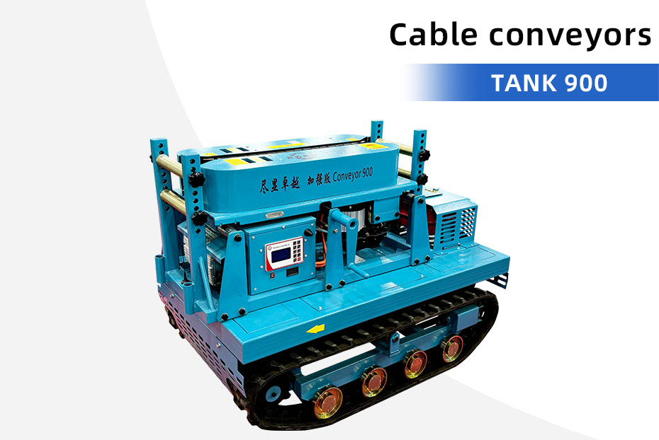
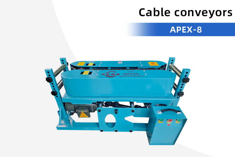
The published APEX-8 specification lists two 1500W motors, 19.2 m/min conveying speed, 6000N maximum tension and a 2–24 cm cable diameter range. These figures help identify a candidate machine, but do not establish a permissible cable load or a guaranteed installation distance.
The LayPro 900 Double voltage table lists a different speed range and electrical configuration. Do not treat it as interchangeable with the APEX-8 just because both are cable conveyors. Compare the fixed and variable speed specifications and confirm the actual controls for the proposed combination.
What must be confirmed for multi-unit operation?
- The exact machine models and quantities in the proposed layout.
- Compatible controllers and the supplied interconnection equipment.
- How operators coordinate start, stop and changes in operating conditions under the manufacturer’s procedure.
- The inspection, communication and stop arrangements in the approved method statement.
Ask for written configuration details. Several machines on one route do not automatically constitute a synchronized system, and their catalogue force values are not a simple total that the cable can safely accept.
What should you send for a quantity proposal?
Send an annotated route drawing, cable datasheet, photographs of candidate positions, site power information, intended installation method and destination. Ask the supplier to state assumptions and any missing information rather than supplying an unexplained quantity.
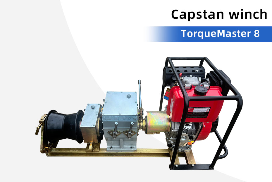
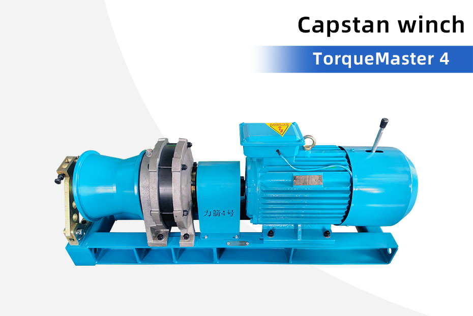
Request a project-specific cable pusher configuration. If the arrangement may also involve pulling equipment, read cable pusher versus cable pulling winch before preparing the enquiry.